Basic St. Andrews Cross - BDSM furniture Workshop
articles and tutorials BDSM workshop
Basic Cross
Cross Body
The first step is making the cross body from two pieces of lumber. While 2x4s can be used, I don't recommend it. Decent quality 2x6s are a good choice, as are 4x4s. Fancier crosses can be made from hardwoods, and more substantial ones from larger structural lumber.
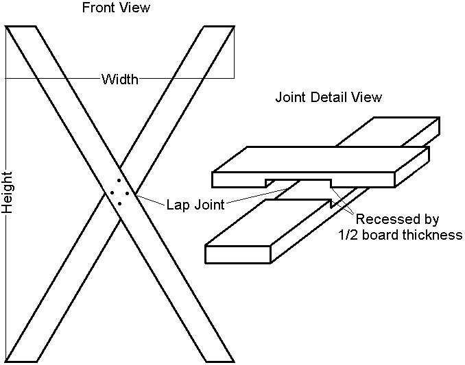
The boards connect using a lap joint (see diagram) in which half of the thickness of each board is removed. They lock securely together if the grooves are tight.
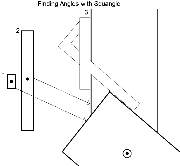
One way to mark these grooves is the following, using a neat tool called a Squangle and a spare piece of your body stock:
1 - Mark and drill a 3/8" hole centered across the breadth of the spare board (A), roughly in the center of its length.
2 - Place a mark dead center on the broad side on a body beam (B), centered lengthwise and across the board's breadth.
3 - Set the Squangle to 90-[your target angle]... for example, 90 - 38 = 52. Place Squangle and board A in position shown, atop board B such that you can see the dot through the hole. Carefully mark both sides of board A on board B.
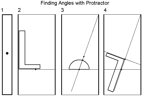
Using a protractor is also simple, although I find it less exact. Numbers in this paragraph reference the diagram below. Mark dead center of the beam (1). Draw a right-angle line through this point. Center the protractor along the line and over the dot, and mark out 90-[your target angle] (2). Draw this line and mark 1/2 the width of your beam from the original mark along it (3). Draw a third line perpendicular to the second, through the second mark (4). This is one edge of the groove. Use a spare piece of leg stock to mark the other edge a board's width away.
Cut this groove to half the thickness of the board, staying slightly within the lines. You can widen and/or deepen it later, but obviously can't put wood back on. Use either a table saw with dado blade or a router. If you don't have either of these tools, it is possible to make the cut with many passes of a circular saw or by hand.
Make identical grooves on both body boards. Test the fit, and adjust one or both grooves as necessary. You are aiming for tight fit without splitting the wood. A "firm push" should be required to assemble the body. With the X together, mark and drill four holes in the pattern shown on another configuration that meets your needs. Avoid two holes close together along the same grain line (and don't forget that the grin runs differently on the back board!). Use a 1" spade bit to recess an area around all four holes to a 1/4" depth, preventing the bolt heads from stabbing the occupant. Smooth the insides and edges of these recesses with sandpaper.
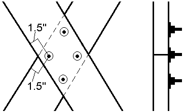
Note that in a properly constructed body, there is relatively little stress (and no shearing stress) on these bolts. The primary force, that pushing apart the angle between the body's beams, is taken by the joint, not the bolts. This situation changes if these bolts are used to secure the upper end of the rear leg. If this is your intent, consider modifying the bolt pattern to get 3 or 4 bolts through the rear leg hinge. Don't glue this joint... it's unecessary, and would obviously make it difficult to disassemble ;).
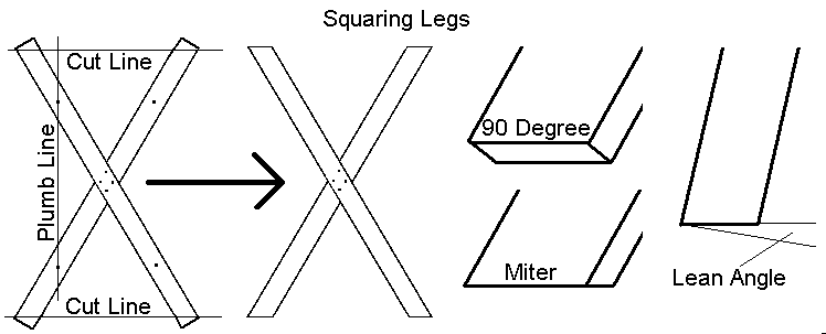
The last step for the body is squaring all four "legs", or board ends, to the ground. Use a plumb line and a straightedge (a straight 1x4 works fine), and work on a level floor. First, hang a plumb line from the ceiling... a simple string with a weight on it works fine. Next, mark a point out the same distance from the center of the body on each leg. Stand the cross up behind the plumb line, and shim it (if necessary) so that the two points on one side are on the line, as shown below. Place your straightedge parallel to the floor and mark cut lines across the base of the cross. Flip the body and repeat. Note that this approach squares the cross, even if the previous work isn't exact. If you're building a cross with fixed lean, you might want to miter the bottom legs to that angle, as shown.
Rear Leg(s)
There are many different options for the rear support design. Pick one that meets your needs. The diagram below shows a few, both fixed and folding.
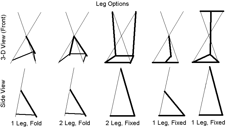
I see a lot of crosses with horizontal bracing across the top and/or bottom of the body. This is really unnecessary if the body is built correctly, and adds to the weight, complexity, and cost of the piece. Unless you're doing a fixed design and don't plan to move the cross much, avoid it.
Fixed supports will provide more strength and stability at the expense of portability. They are certainly the best choice for pro spaces and heavy players with a dedicated dungeon. A folding support design is really advantageous if you move or hide your equipment. With the supports folded in, a cross will slide under a bed or into a closet. Also, fixed-leg crosses don't allow adjustment of the lean angle, which limits your play flexibility a bit. A single lean angle, usually about 20 degrees, is still going to be used most often though.
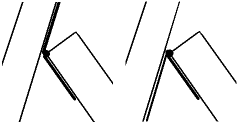
In the single/folding design, the leg should be 2x6 or 4x4 as it takes significant compression force at all usable angles and bending force in more tilted positions. It bolts to the body with a very heavy hinge, either using two of the four body bolts or 2 to 4 of it's own. In the former case, increase the size of these bolts. Align the hinge so the leg folds flat to the cross body, as shown, and bolts holding it go through the grain (not into the end grain).
One disadvantage of the single-leg design is that the either leg protrudes beyond the bottom of the base in a folded position or creates a relatively small base area. The 2 leg folding design can limit or eliminate this problem. Each leg bolts to a single body board with a heavy hinge, and swings out at the same angle. Again, use the body bolts on the hinge if possible. Because two legs share the load and the square base area is larger than the single-leg triangle, this is a more stable design.
Next, we need to connect the bottom of the support leg(s) to the bottom of the base legs. These parts are medium lines in the Options diagram above. There is only one direction of force to contend with... that in which the hinge opens. The simplest solution is a length of chain, connecting with a quick link at both ends. This approach allows easy adjustment of the lean angle.
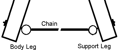
Put an eyebolt throught the wood at each end of this linkage, using a sizable washer. Don't use a screw-eye, although a very heavy plate staple with equally heavy lag bolts is an option. If using an eyebolt, recess the nut in the front of your cross body. In either single or double leg design, you'll use two lengths of chain.


