Kneeling Post - BDSM Workshop


articles and tutorials BDSM workshop
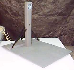
The kneeling post is designed to restrain someone in a kneeling position, which as you might imagine can be quite severe over time. The project is relatively simple... just a square of plywood with a rigid 4x4 post sticking up from it. However, you may want to install padding on the base and one side of the post.
Difficulty: Low
Steps
Modify Design
The overall design of the kneeling post, including dimensions, is below. It has been sized to fit most people. However, if you plan to kneel a very large (in any dimension) person on it, you should check the measurements, particularly the post height and base depth. Also, if you like a very wide kneeling position, check the base width to ensure knees don't hang off.
Post
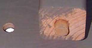
Start by making the post itself. First, cut a 4x4 to length. Make especially sure that the bottom end is square and flat. Next, glue a 1" dowel, 6" long, into the bottom end. Drill the hole carefully, and glue in place. Cut protruding end down to slightly less than .75". See diagram and picture.
Base
The base should be high quality 3/4" plywood. Cut it to size, according to your design. Locate the center of the post position and drill a 1" hole to receive the dowel. Test the post and base by assembling.
Cut the two support beams, Beam 1 and Beam 2 in the overview diagram. Beam 1 runs across the base, and is 2x4x[base width]. In my design, this is 2x4x36". Beam 2 runs from Beam 1 to the rear of base, centered across the base width. It is 2x4x7.5". Drill three 3/8" holes across the 4" width of these beams: 2" in from both ends of Beam 1, and 1.5" in from one end of Beam 2. The diagram under Struts below shows where these holes are located.
With the post and base together and the post directly vertical, clamp Beam 1 (2x4x[base width]) in the location indicated. Apply wood glue to the underside of Beam 1 before putting it in place. Remove post, flip, and secure beam 1 to base with countersunk screws. Glue/screw Beam 2 (2x4x7.5") in place with the hole towards rear of base. Let dry overnight, and your base is assembled.
Struts
Three steel struts hold the post vertical. Each is a length of 1x3/16" steel. They bolt to the two beams using 3/8" bolts, into the positions shown in the overview diagram (dark lines).
The first two (side-to-side) struts are the longest, and should fold down to reach the far side of the base. They both connect to the post using a single bolt recessed into the front of the post. The third strut runs from the end of Beam 2 about half way up the post. It connects there using another bolt. Strut 3 must be removed from the base for complete disassembly, since Beam 1 keeps it from folding flat.
Cut the struts to length from steel stock. Round and smooth all corners and edges. Drill two 3/8" holes in each strut, 1/2" from the ends. Bolt the struts to the correct locations on the beams, keeping the bolts a bit loose. Set the post in place.
Keep the post at exactly 90 degrees to the base while marking 2 holes for the upper strut bolts. Mark the hole for struts 1 & 2 using _both_ struts to find the location, and make sure they'll both be tight. Drill these holes with a 3/8" bit. Coutersink the front hole 1/4" with a 1" spade bit. This prevent the bolt head from stabbing anyone!. See diagram above.
Finishing Up
Do a lot of sanding, especially on the front area of base and the post. Make sure all corners are rounded and that there aren't any splinters awaiting a victim. Finish with paint or stain.
As mentioned above, padding is a good idea. You can either throw down towels/blankets, make a removable pad from foam and covering, or upholster permanently. If possible, pad both the front area of the base and the front surface of the post. Upholstery is the best approach, in my opinion. Leave room to access the head of the bolt holding struts 1 & 2 in the front of the post.
Put in a number of tie-points, using eye screws in your favorite size. Some possible locations are noted in the diagram below. Using these points, near-total immobilization is possible.