TFM v2 - Fucker - BDSM furniture Workshop


articles and tutorials BDSM workshop
The main issue in fucking machine thusting is converting circular motion, provided by an electric motor, to linear motion. There are a couple of ways to accomplish this. In the original TFM, I used a plate/pivot/direct drive arm mechanism. It worked, but required a lot of space to be efficient. This second-generation design uses a pin-and-channel method that is more compact, though somewhat noisy.
My objective was to build a powerful and relentless unit that was relatively portable.
Difficulty: Moderate
Special Tools and Materials
This project requires basic wood and metal working tools.
One special material: a gear motor. You need a relatively powerful (1/20th HP) 120v electric motor with gear-reduction box. Final drive shaft output should be about 60 RPM. This motor will probably cost at least $100 new, although I found one used for $30. Search local salvage yards.
An update note. I was going to better and better motors over the years, looking for more power, quieter running, and the durability for extreme sessions. I finally gave in to using industrial DC gearmotors that start at about $200 and go practically to infinity. I also look for at least 160 RPM these days... sometimes, faster simply IS better ;) Check out the motors and parts page for more information about motor recommendations.
Design
Motor Mount
Most motors of this type have four threaded mounting holes on the front face, same side as the drive shaft. I used two steel L-brackets, each bolted into two of these holes. Of course, you have to drill matching holes in each L-bracket. Aim for minimal clearance beneath the motor.
Pin Drive
Step two is to attach something to the drive shaft that has an off-center pin protruding by about 1". Start with a 1.5 - 2" pulley made for the shaft diameter of your motor (mine is .5"). Use four stainless steel self-tapping (S/T in diagram) screws to secure a plate to this pulley. Drill pilot holes first, of course. I found a square industrial washer, 1/4" thick and 3" square, that works well. Finally, attach a nylon roller with a stainless steel bolt. The roller is the pin, and using nylon quiets it down considerably. The pulley will secure to the drive shaft with an allen screw.
The distance marked A in the diagram above is critical. This is half the total stroke distance. I've had good results with A=1.5", giving a stroke depth of 3". You can also drill multiple holes around the washer.. moving the pin assembly changes stroke depth.
Channel Assembly
The channel assembly is built from several pieces of steel, bolted together. The pieces I used are as follows:
- Drive arm. 1" x 3/16" cold-rolled steel, X" long.
- Channel half (2). 3/4" x 3/4" cold-rolled steel angle, 4" long. Length must be at least 1/2" longer than stroke depth.
- Brace. Any small piece of steel braces between the two channels.
It is critical that a) the channel halves are equidistant over their length, b) that distance is just a bit more than the diameter of your pin, and c) they remain in exactly this position. The pin must be able to move freely in the channel without undue vertical play.
B is the channel width, and is slightly more than the diameter of the pin. Bolt the pieces together as shown in the diagram above. Tighten and double-nut these bolts. Trim any bolt that extends past the second nut, and smooth all rough edges. Makes sure the pin can move freely across the entire channel!
Bushing
The bushing holds the channel assembly firmly in two directions (front/back and side/side) while letting it move freely in the third (up/down). It must be built to tight tolerances to keep the drive arm moving in a straight line and plane. Again, it is bolted together from several pieces of metal:
- Angle bracket. 2" wide steel angle bracket, 4" on each arm. This should be heavy steel.
- Sides (2). 4" lengths of 1/8 x 1/2" steel.
- Plate. 2" wide steel place, 4" long. I cut mine from another angle bracket.
Note that the sides are not as thick as the drive arm. Use thin washers to increase spacing to just over 3/16", the thickness of the drive arm. The distance C above is slightly greater than the width of the drive arm. The result: a bushing through which the drive arm slides while remaining quite straight. Ideally, lubricate the interior with a teflon-carrying oil. Tighten the bolts, and trim them if they extend beyond the nut. Smooth all rough edges.
Wiring
The wiring is very straightforward. You need a heavy-gauge cord with plug (grounded is a good idea), a light switch, switch plate, junction box, and a bit of 8-10 gauge insulated wire.
In the diagram above, note where the wires enter and exit the junction box. If using a grounded plug, the ground wire should be connected to the motor, junction box, and the ground connector on the switch.
Case
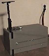
In addition to aesthetics, the case serves one critical function: it holds the bushing rigidly at the right location to keep the pin in the channel. Design any box you'd like. Here is mine:
This is a five-sided box, with what I consider the "front" left open, constructed of 1" white pine. The motor and junction box are secured to a double-thickness bottom, and the top lifts off to provide access to the motor. The top secures to the bottom with four 1/4" lag bolts, indicated by the heavy lines in the diagram at right. The bottom fits into rabbits on both sides to give a tight, strong fit. The bushing screws onto the top with thumbscrews, heavy lines in the left diagram. This approach allows easy disassembly for transport. The entire box measures X" x X" on the outside, just large enough to hold required parts.
I finished my case with a lot of sanding and two coats of grey paint. I didn't paint the sides of the bottom nor the interior of the rabbits on the sides, since the fit was already very tight.
Finishing Up
One last thing to build... a way to attach a dildo. I chose to build a metal platform, using the remaining chunk of angle bracket from the bushing work and another space piece of angle iron. Very simple bolt-together job, as shown below.
A dildo can be securely tied or strapped to this platform. You need to drill matching holes in the vertical member of the platform and the upper portion of the drive arm to bolt the two together. Another nice addition is an arm extender, a piece of 1" x 3/16" metal that bolts between drive arm and platform and extends the drive arm.
I painted the bushing (except interior) and mount with a flat black epoxy, and made a velcro strap for rapid dildo exchange.
Pitfalls and Challenges
The TFM v2 drive design (pin-and-channel) is more challenging to build than the flexible drive arm. Several components have critical-level accuracy requirements:
- The pin must be square to the drive plate. Screw up here and you're hosed... buy a new plate immediately.
- The channel width must be at least the width of the pin along it's entire length. However, make it too wide and the mechanism will bang around on each revolution.
- The bushing needs to be tight and accurate. Otherwise, the pin might either leave the channel or hang on the bolts holding channel pieces to drive arm.
To get the channel right, I had to overdrill the holes for channel bolts. This allowed some flexibility in positioning the channel. After making sure both sides were tight (but not binding) to the pin, I cranked the bolts down to hold it in place. Only after this step did I drill the holes for the brace.
Note that soft steel is somewhat malleable. I accidentally dropped the entire arm assembly once, and it landed on one end of a channel. The channel bent. After a bit of work with a hammer I got it back in shape, but made sure not to drop that again!
The Finished TFM v2
Back to Fucking Machines