The Fucking Machine v3 Concept - BDSM furniture Workshop


articles and tutorials BDSM workshop
Eventually, and perhaps next, I'm going to extend the Fucking Machine into version 3. Almost everyone is probably familiar with the Sybian, a half-barrel-shaped machine with a squirming dildo and vibrating clit pad. I plan to add both features to TFM, making it a vibrating/squirming/fucking machine. Each capability will be an independant system with its own speed-controlled motor.
Original Concept
Here's the original concept diagram, which I put on the web for comments and ideas. I received some good ones, and did some more thinking myself. A few tweaks are outlined in the next section.
The vibrating system, in green. Going with the simple approach, I plan to find and destroy an orbital sander and hook its guts to a shock-mounted plate. Due to space constraints within the half-barrel, this will be a two-part plate. The inside piece will extend a fair ways towards the front of TFMv3, allowing the vibrating mechanism to be located forward. This piece is shock-mounted with rubber bushings to the case. A smaller external plate will be firmly mounted to the inside piece. I haven't determined the right shape for the business end. This motor will turn quite rapidly to produce good vibrations.
The squirm mechanism, in blue. The key piece here is the 1/4" steel rod. The upper 6-8 inches go into the center of a big dildo, and are bent to create the "squirm" when turned. The dildo itself doesn't turn... it squirms. The rod is held in place by two mounted bearings. Drive is through a pair of 45-degree bevel gears, one on the rod and another on the motor. Final drive should top out at ~120 RPM, so these gears need to ratio motor speed to this target. All of these components are mounted in a narrow, rigid steel frame.
The thrust mechanism, in red. The thrust component treats the squirm mechanism (and attached dildo) as a single unit, and moves the whole thing up and down along two vertical rails. I'm considering commercial drawer rails to provide a smooth glide. Upward motion is provided by a drive pin on a pulley, similar to the TFMv1 design. Downward motion provided by gravity. I'm planning a belt drive to turn the pulley, both to conserve width and to keep some stress off the (more expensive) motor bearings. Final drive should top out at about 100 RPM (a little faster than TFMv2, BTW).
The case will be similar to Sybian's... a half-barrel of wood. Three controls, one for the speed of each motor. Progress will, of course, be posted here.
Concept Revised
I started building TFM v3 a piece at a time about a month ago (concurrent with other projects). Every piece to-date (squirm and thrust) has been tested and reworked and tested again. I share some of the changes below.
Here is a revised concept diagram reflecting design changes. Following that is is picture of the subframe assembly as it exists today (yes, this ugly thing actually works ;). I've labeled some of the parts for clarity. Note that TFM v3 has a DC motor. Although you can't see the rectifier that converts AC to DC, the filtering capacitor is readily apparent. For scale reference, this capacitor is about as big around as a beer can, though somewhat shorter.
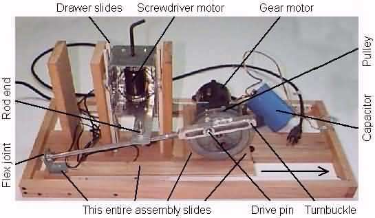
Squirm: I built the design shown in the original diagram at top, and it worked fine. However, the entire assembly was too heavy and complex to recommend. I've redirected my efforts at this time. I cut off the top half of a cordless screwdriver, resulting in a small, light, powerful motor and gear system. This will be powered by guts from a DC wall pack (transformer and rectifier) plus voltage regulation system, to be described at a later date. The screwdriver is mounted in a steel frame. The screwdriver came with a drive connector for 1/4" hex stock, used in standard screwdriver bits. I'm using a 1/4" hex key as the actual squirm rod, which will be straightenned most of the way.
The drawer slides worked, but not quite as expected. The sliding action was quite smooth, but these rails are only secure in one direction (originally, down). Result: the squirm unit flops to one side on each stroke. Unacceptable. I have since added a second pair of drawer slides, facing the opposite direction. This results in a smooth, stable slide. If I were doing this again, I would look into the slide mechanisms intended for pocket doors, the ones that slide into the center of a wall. These hold the object from movement in both directions, and a single pair should suffice.
Thrust: I decided to add run-time depth adjustability to the TFM v3 thrust mechanism. The new approach is as follows. A pulley is attached to the motor (the pulley from TFM v1, actually), and has a pin very similar to TFM v2. This pin runs in the cut channel of an aluminum turnbuckle frame. A 3/8" rod screws directly into the turnbuckle. The opposite end has a flex-mount. While running, the entire rod moves up and down. Vertical move distance varies from very little (near the flex mount) to about 3" (near the turnbuckle). All of the things described so far are mounted on an L-shaped frame that slides relative to the tower that houses vertical rails depicted above. Again, this sliding frame uses drawer rails.
A steel arm protrudes from the squirm case, ending directly above the line of the thrust rod. This arm holds something called a "rod end"... basically a machined eyebolt with a drilled bearing permanently inset into the eye, and able to rotate over a wide angle in all directions. The rod runs through the 3/8" hole in this bearing. This transfers vertical motion to the squirm unit, which runs in the tracks as originally described.
Back to Fucking Machines