TFM v4 - ThumpStir Pictures - BDSM furniture Workshop


articles and tutorials BDSM workshop
The following series of pictures illustrates the components of TFM v4 and their assembly.
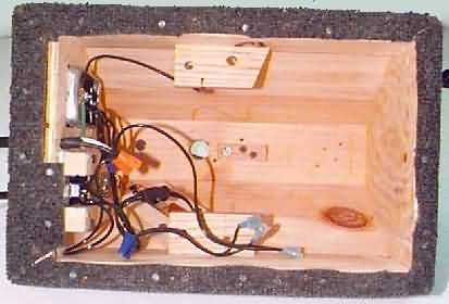
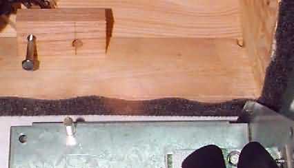
First, a look at the bottom of the enclosure with the removable pieces out of the way. The thumper electronics are mounted in slotted boards. Circuit board #2 was first mounted to a customized wall plate that also holds the new thumper on/off switch. The squirm switch is in the junction box. Also note the two squirm unit mounting blocks, one along either side, and the bushing in the center of the unit top. The larger hole in top is for the thumper shaft. It's this big to allow the unit t tilt (adjust).
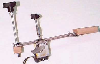
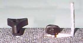
Next two pics are of the thumper unit on its mount, with accessories (nub and adjusting knob) screwed in. These must be unscrewed to mount the unit. The block at right is what screws to the underside of the 2x4.
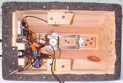
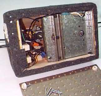
Here is the underside of the enclosure again. This time, the thumper unit has been mounted using four screws, and the adjusting knob has been screwed into it from the top.
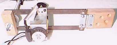
Next, a close-up of the squirm mounting brackets. The open hole fits the short post (used to be long, but was cut off) on the squirm unit. The bolt goes in the position shown, running through holes drilled in both layers of the squirm unit.
Underside again. Now the squirm unit has been bolted in place and hooked to its leads. After this step, the upper squirm shaft is screwed into the squirm stick (while the bottom is off!). The bottom screws on, and has four rubber feet to maintain ventilation clearance.
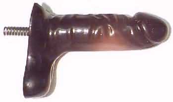
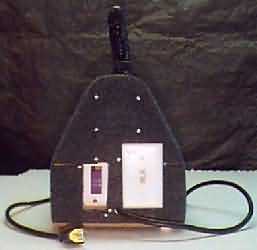
Here is a view of the top without dildo, and the dildo itself. On top from left to right are: thumper adjustment knob, thumper nub, and squirm shaft.
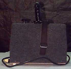
Front and side views of the assembled unit.
TFM v4 - ThumpStir Project Page