TFM v4 - ThumpStir - BDSM furniture Workshop


articles and tutorials BDSM workshop
In TFM v4, I took a different approach. The idea came from the discover of a pasta-making machine at the local Salvation Army. I bought it for $9 without knowing what to do with it. A bit later, I came across a close-out "thumping" style massage unit at a bargain store ($16). These two unlikely pervertables provide about 90% of the guts of TFM v4. Next, a bit more description of the two found items and what got used in case you plan to look for similar things.
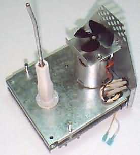
The pasta maker is simply metal guts with a plastic cover and some accessory pieces. Cover and all accessories except stir stick go straight into the trash. The result is a large metal "L" shaped frame holding the motor and a three-stage gear system that reduces speed to about 60 RPMs. The final gear has a square receptacle that holds the stir stick. The stick itself seemed like the easiest way to transfer power, and modifying it is described later. Directional switch and "make sure the lid is on" switch were both discarded. This thing is designed to mix pasta dough, then push the stiff stuff through little holes. It's nicely powerful, and easily up to the task at hand.
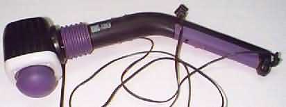
The business unit in the massager is basically an electromagnet with a rod through it's core. Disassembly was fairly complex, since there are lots of little pieces screwed, glued, and melted together. It's all scrap, except for the electronics (on two circuit boards), electromagnet, and rod. The thing had two switches, one on each board. The first is power. The second changes thump speed between three positions (very slow, medium, and remarkably fast). I used the speed switch, leaving it mounted, and left the on-off switch in the ON position. A new switch feeds power to the first board.
Difficulty: Moderate
Special Tools and Materials
Components similar to the two described above. Hunt around for bargains.
Design
Thumper Mount
An interesting characteristic of the thumper mechanism is that the harder it's pressed against something, the harder it thumps back. It makes sense to capitalize on this capability by mounting it so an operator can raise and lower the business end. Here's a diagram of the design I used:
Thumper Nub
To focus the thumping, I wanted a small, hard nub on the end of the rod. However, it's height should be adjustable at least a bit, independant of the entire mechanism. I used duck tape as a foundation and forced on a 1/4" joining nut. A short length of threaded rod screws in here, and a shaped knob (with 1/4" inset) goes on the other end. Either end of the rod can be unscrewed slightly to change height, and a longer length of rod can be substituted for major changes. Make sure that the lower end of the joining nut doesn't interfere with the maximum travel of the thumper shaft.
Squirm Shaft
The squirm assembly comes basically complete out of the pasta machine. However, we need a way to attach a length of 1/4" rod to the final drive. I chose to use the stir stick that came with the machine, since it fits securely into the square recess described above.
It needs some preparation. First, cut of all of the protruding arms and the screw end. Square off the top, and drill a hole in its center... this hole mst be perfectly parallel to the sides of the stick. Epoxy in a threaded brass inset with 1/4" inner threads. The final piece of the squirm rod is the correct length of a 1/4" bolt. This bolt is bent slight in the final step, as shown, to create dildo movement as the rod turns.
Squirm Bushing
The upper squirm shaft (1/4") runs through a bushing to keep it from moving laterally. While the dildo itself could perform this function, I feel the bushing necessary for maximum stability. This is simply a flanged, 1/4" I.D. bronze bushing mounted on a piece of oak. The oak is screwed to the underside of the 2x4 in the appropriate location.
Enclosure
I built a simple enclosure around these components using a 2x4 (across the top), 3/4" plywood (ends), and 1" pine (sides). The enclosure width is based on the width of the squirm unit. As this component rests against the back end, it also determines the distance from back to dildo. I made total length such that the front-to-dildo distance is about the same. See diagram.
The rounded edges were shaped using a plane and belt sander. A smooth finish isn't critical, since the whole thing is going to be covered with carpet anyway. Note that the 2x4 sits atop one thickness of plywood at each end, providing a great deal of strength. A recess was carved into the thumper exit hole atop the 2x4, providing freedom of movement downward.
The double-thick end holds the three switches (thumper on/off, thumper speed, squirm speed). I custom-cut a wall plate to hold the two thumper switches... the on/off is a micro-toggle switch rated at 10 amps. The two circuit boards are mounted in grooved blocks of wood screwed to the enclosure. A couple dabs of silicone prevent them from rattling about.
The 5 amp continuous range motor speed control that feeds the squirm unit is mounted in a standard steel junction box. The power cord also comes in through this side. It friction fits through a hole near the bottom.
I used perfboard for the bottom. This provides some ventilation, stirred about by a fan blade on the back end of the squirm motor. Both the squirm motor and thumper electromagnet generate some heat.
Mounting Things
The squirm unit fits tightly into position. It rests against oak blocks towards the front, and 1/4" bolts hold it firmly (but not tightly, as tightenning binds the gears) in place.
The thumper unit is screwed to the underside of the 2x4. Adjusting screw goes through the 2x4 to a knob on top-front. The two thumper circuit boards mount using scrap pieces of pine cut with shallow grooves. Circuit board #1 (with unused on/off switch) screws to a free spot inside the case. Circuit board #2 is mounted to the face plate holding both switches with two such boards.
Finishing Up
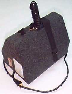
Finishing up was fairly simple. First, I screwed a length of 1.5" nylon strap to each side, forming a simple belt to hold a dildo in place.
I covered the entire outside with dark grey interior/exterior carpet, tacked in place on bottom and ends. The base screws to the bottom, and I included four little rubber feet to allow air movement. At the time of the writing, I still need to paint the few areas of exposed wood (interior of thumper switch recess, thumper areas on top, and edges of the perfoboard bottom) black.
The Dildo
Any didlo will work with TFM v4, but it needs some simple modification. First, drill a hole straight up the middle of the didlo from the base. I used an 11/32" bit. It's a little tricky to hold a dildo perfectly vertical, bottom-up. I prepared a length of ABS pipe into which the didlo fit firmly, which sufficed. This hole needs to be at least 3" deep.
Into this hole, shove a length of moderately stiff spring. The spring should have an inner diameter of 1/4" or slightly more. The squirm rod needs to move freely within this spring. I left about 1" of spring protruding from the dildo... it fits into the original squirm access hole and helps to hold the dildo in place.
As the final step, cut the upper squirm rod to length from 1/4" bolt. It should screw all of the way into the lower squirm shaft, and end just short of the top of the spring when the dildo is in place. Round and smooth the cut end. Bend this rod slightly right at the base of the dildo to create the squirming motion.
The Finished TFM v4
Assembly sequence and componentsBack to Fucking Machines