Frame Stocks - BDSM furniture Workshop


articles and tutorials BDSM workshop
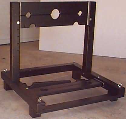
This is a free-standing stock, and a very flexible design. The upper two stock boards lock in the neck and wrists. By lowering these two boards, the third comes into play. In this position, these three boards can restrain ankles and wrists (and head, if your occupant is very flexible). The horizontal stock boards can restrain the ankles, possibly in combination with the head, wrists, or both.
A number of other modifications are possible, and we'll talk about these options after the plan.
Difficulty: Difficult
Review Design
First, familiarize yourself with the general design. Joint accuracy is critical to the piece, particularly the junctions between uprights and horizontal legs. Using a dado/lap joint here provides excellent rigidity if done right.
Stock boards referenced below as 1 and 2 are 2x6 fir, and 3, 4, 5 are 2x4. All five pieces are the same length. The four pieces comprising two subframe assemblies and read brace are 4x4 fir. The front crossmember is a length of 2x4. The four feet act as spacers, providing enough clearance for the feet beneath the lower ankle holes. These are short lengths of 4x4, and are glued to the horizontal legs. Heavy black line is steel bar stock.
Each stock board has half-circles cut into it (none has an entire circle). Numbers 1, 2, 4, and 5 slide in channels cut into their respective 4x4s, and bolt in place during use. I've chosen to use aluminum U-channel fitting into parallel groove for the slide mechanism. It's also possible to cut 1.5" x 1.5" grooves to receive the ends of the 2xX stock directly. However, a metal-to-wood channel is much smoother and stable than a wood-to-wood equivalent when pieces are this large, as I discovered in testing.
Measurements
You need to start with a few measurements of your target occupant. If you plan to build generically, measure a handful of people and use your judgement. Size the holes with these: a) wrists, b) ankles, c) neck. Identify minimum frame height based on how far off the ground their head is when comfortably bent over. Space upper holes (on crossmembers 1 and 2) by having them comfortably raise wrists into line with neck. Space lower holes (on both 2/3 and 4/5) at a mild straddle. Measure from floor to just above the bony nub on their ankle, indicated by the filled circle, to get minimum ankle height. See diagram below, and don't make fun of my stick figures!
This information provides the basis for completing the design. Wrist-to-wrist (upper spacing in diagram) is likely to be longer than ankle-to-ankle, and this is the determining factor in overall unit width. Add 12" (6" per side) for spacing and you have the width of boards 1-5. Height bent over gives minimum vertical to the top of board 2. Lower spacing plus 3.5" (width of board 5) gives the minimum length of the longer side of frame bottoms. Short side of frame bottoms need to be about half of this for stability. The four legs need to be long enough that the lowest edge of stock boards 4 & 5 are at least the ankle height from the floor.
Finish the design after reading the rest of the plan.
Cut Wood
Stock Boards and Metal Channels
Cut the stock boards with holes first (1-5). Two lenghts of 2x6 and three of 2x4. Select this wood carefully, especially avoiding warp across the long side of the cross-section (i.e. 6-inch side). Mark and cut the half-circles in their respective places. Remove most of the wood with a jig or scroll saw and finish up with drum sanding.
Cut and smooth 10 segments of channel stock (metal). Four fit to the ends of the 2x6s, and are roughly 5.5" long. The rest are 3.5" or so, fitting to the 2x4s. Round the corners, or they may dig into the wood of your grooves.
Frame Pieces
The segments of the frame require more work. First, cut the two horizontal legs and two uprights from 4x4 stock. Next, you need to remove some wood from these pieces. The following steps can be accomplished on a table saw with a dado blade, a router, or as a last resort with standard table saw blade and chisel.
First, run two grooves the entire length of the uprights, on the inside face. Spacing , width, and depth are determined by your metal channel material. Channel depth should be about 1/4" less than the depth of the metal stock, providing clearance for the bolt at bottom. Width may need to be as much as twice the metal thickness for a smooth slide. Boards 1 - 3 run in this channel, and they should slide freely. See diagram.
Cut a lap in the outside bottom of each upright as shown below. This lap should be about 1.75" by 3.5", but exact width should be slightly less than the width of respective horizontal leg.
The horizontal legs need several cuts in the order shown below. First, cut a 1.75" deep by 3.5" wide dado to receive the vertical member. Actual width of this dado should be a hair less than the board it receives. Exact depth should result in an even fit with the respective upright lap. Note that this is a custom-fit process, and means one upright is always associated with a specific leg. Next, run channels down the front inside face of the board, as shown. These are identical to those in the uprights, and receive boards 4 & 5. They stop at the dado you cut previously.. this is easy using a router, but requires a pull-off and set-down process on a table saw. Finally, cut a 1.75" deep and 3.5" wide lap to receive the rear brace. See diagram for clarification, and remember that these boards are _mirror images_ of each other!
If you don't have the tools for these approaches, you can simulate the same frame from multiple pieces of wood, as shown in the diagram below (one half of frame depicted). However, using this approach the stock board ends will slide in the resulting channels. As I indicated earlier, I don't like this approach.
This set of channels allows the following. Boards 1, 2, and 3 can slide to any location along the vertical channels. Boards 4 and 5 slide along the horizontal channel up to the upright.
Crossmember Braces
Cut the two remaining crossmembers, the front from 2x4 stock and the back from 4x4. Length of these boards is the width of the total frame. Identify this distance by attaching metal channels to board 4 ( used three countersunk drywall screws per segment) and placing it snugly between the horizontal legs, within the channel grooves. Measure between outside edges of horizontal legs. In the 2x4 (front brace), cut a .75" deep lap, width = width of the horizontal legs. In the 4x4 (rear brace), cut a lap to mate with the laps in rear of horizontal legs. See diagrams.
Feet
Four short feet contact the floor, and should be made from 4x4 stock. They are identical, and dimensioned to provide the required ankle clearance. See the diagram in next section.
Assembly
1. Bottom frame
Do a mock assembly of the entire bottom section of the unit on a flat surface, ensuring that your joints fit and are square. Adjust joints as necessary. Mark locations and drill a 3/8" hole in each corner. Make sure not to interfere with the channels in the front section. Drop bolts into these holes and check squareness again. Also, make sure that a stock board slides neatly into place. Adjust as necessary.
Disassemble and continue with the next step. You might want to recess the tops of these four holes slightly with a 1" spade or forstner bit to accept a washer permanently. Optional, but a nice touch.
2. Uprights
Time to join the uprights to the horizontal legs. Make sure these joints fit tightly and are square. While the pieces are clamped together, drill a 3/8" hole dead-center of the intersection. This should be directly between the two channel grooves on the upright.
Again, use a 1" bit to recess both sides of these holes. Depth should equal the thickness of nut + washer. The recess on the inside face of the upright is required to provide clearance for the sliding stock boards. The outside recess is optional.
3. Feet to Legs
Glue the four feet to the undersides of the horizontal legs, about 3.5" back from the ends. This leaves enough clearance to attach the brace members of the bottom frame. Best approach is to reassemble the bottm frame, inverted, and glue. Liquid Nails is a good choice for this attachment. See diagram.
4. Upper Brace
You should have the frame basically assembled at this point. Time to cut and secure the upper brace. Measure the exact distance between the insides of the two uprights at their bottom. Cut the upper brace to an appropriate length from metal stock (I used 1.25" x 1/8" mild steel), and secure it to mirror this distance near the top of the uprights. I used 1/4" x 1" lag bolts. Don't bolt through a channel! Make sure a stock board (with metal channels, of course) slides freely along both horizontal and vertical channels. Now is the time to fix it, if there is a problem. "Fixing" means modifying the channels themselves at this point. Once both channels allow free movement along their length when the frame is assembled, you can move to the next step.
4. Lock Holes
If you haven't done so already, screw the metal channel segments to the ends of board 2. You'll have to remove them (and the ones on board 4) for finishing, but need to drill through them first.
Stock boards 2 and 4 lock in place within their respective channels at specific places, using 5/16" bolts running through 4x4 frame and the metal channel. You can drill as many of these holes as desired for flexibility, as long as they're not closer together than an inch or so. The only _required_ position is with board 2 all the way down against board 3 (unless you don't want to use the vertical ankle holes).
The first holes for both of these boards should be drilled with the board in place, creating matching holes in 4x4 and metal channel segment. Start by marking a line 3/4" from the edge along each channel, as shown below. All holes must be drilled on this line. Place board in desired position and drill hole using a 3/8" bit. You'll have to use a twist bit for these, since you're going through both wood and metal. Repeat without the crossmember in place for additional locations with a 3/8" spade bit. The difference between hole and bolt sizes provides a bit a wiggle room, and trust me, it's necessary!
5. Closures
Boards 1/3 and 5 secure to 2 and 4 respectively with standard hasp-and staple or locking draw latch. This approach allows the free-floating stock boards to lock to their two fixed cousins at any of the positions you've drilled for.Bolt the fixed boards into any of the positions you created in step 4. Slide each companion board tightly into place. Secure hasp to one board and staple to the other, in any available position that you prefer.
Finishing Up
You still need to round edges, sand out irregularities, and do the standard surface prep for final finishing. Since you've read the plan before starting, you may want to do this to each piece as you go along. Alternately, you can build it as described, then take it apart to sand things. Running some of the sharp edges using a quarter-radius router bit may be a good idea, and is my preference. Coat as usual, with paint, varnish, urethane... whatever your favorite might be. Limit both sanding and coating thinkness within the joints, since they already fit tightly. Attach all hardware, including the metal channels. You are done.
Stock Options ;)
By using parts of this design or adding additional features, you can make a myriad of unique furnishings. Let's look at a couple of ideas:
* Free-form stocks. Using the basic boards 1 and 2 (without ankle holes in 2) with a hasp and hinge, you can very easily make disconnected stocks similar to a yoke or the "violin" of medieval times.
* Doorway stocks. By placing channels (wood or steel) on each side of a doorway, you could avoid the frame entirely for an interesting effect.
* Multi-person stocks. This design could easily be enhanced to hold two people. One way is to make it a "double-wide," securing them side-to-side. A cooler way is to extend the back portion of the horizontal leg and build it identical to the front portion above. One person could occupy the wrist holes while the other is stuck by the head, or you could add more restraining holes. Consider these diagrams:
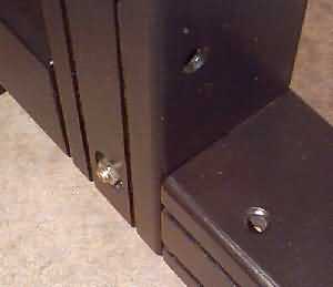
Frame Stocks Pictures
Back to the Stocks Page